
Overview
As we saw in the previous article (Tutorial – How to control motor with The Tactigon – Part I – Hardware), The Tactigon can be connected to a serial motor control board. In this article we’ll look at how to handle it via software (a simple sketch to control motor). The Tactigon will receive commands sent by the controller connected in BLE, and will communicate to the motor control board motor speeds. This part will show the sketch to control motor with The Tactigon ONE.
Sketch
The sketch running on The Tactigon exposes a BLE Characteristic in which the Controller can write in. You can use every BLE Central unit as controller as long as it sends customizable data. The motor board read a single Byte where:
| VALUE | ACTION |
| 0 | Both motors stop |
| 1-127 | Motor 1, 1 Full reverse, 127 Full forward, 64 stop |
| 128-255 | Motor 2, 128 Full reverse, 255 Full forward, 192 stop |
Serial Transmission
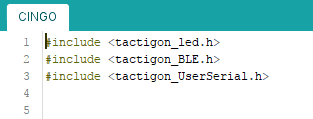
The Tactigon UART library exposes a function to send chars. We use this library to communicate with the motor control board.
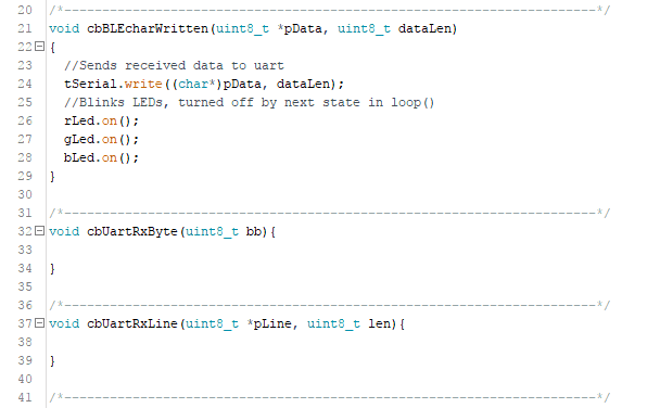
We prepare a callback to be triggered when the BLE Characteristic receives something:
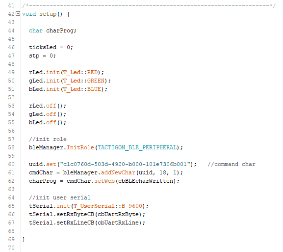
In the setup() we initialize LEDs and turn them off, initialize the BLE Peripheral Mode, create the BLE Characteristic and its UUID, and assign the callbacks created.
Since callbacks handle serial communication, loop() will only cycle LEDs.
Conclusion
The Tactigon UART library gave us the ability to control a tracked rover, but everything with an UART interface can be connected to The Tactigon. Remember to download the sketch to control motor!