
A new application of The Tactigon, this time combined to Raspberry Pi to achieve a futuristic lighting control.
The Tactigon is a board for wearable applications prototyping, able to recognize gestures and different kind of movements, thanks to the firmware availability and simple programming which are typical of the Arduino environment. Now you can see it in another capacity by combining it with Raspberry Pi board in a project born from the need of lights controlling in an environment. For this domotic application we relied on the excellent performance of the “raspberry” board to interact with the intelligent board The Tactigon, in order to control the lights in our office with a few simple gestures.
The connection between the two units is done via Bluetooth Low Energy radio protocol and it’s made possible thanks to the integrated radio chip in both devices and to The Tactigon libraries made available by Next Industries.
In the Raspberry Pi 3 we used BlueZ, with enabled experimental featured, in order to use Bluetooth Low Energy, as well as bluepy library for python.
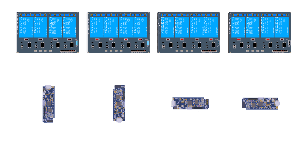
Picture 1
The Project – Lights Control Through Gesture
Let’s go further into details and see how the system is composed; Raspberry Pi 3 is the “brain” of the application ang The Tactigon is the input device; we needed an actuator that physically interacted with the electrical circuit of the lights to be controlled and we found it in a board with 4 relays (sold by Futura Elettronica, www.futurashop.it, with code 2846-RELAY4CH), whose status is set by driving the four TTL inputs provided by the relay board itself.
Relays are equipped with the switch able to drive electrical loads operating at mains, so able to manage light bulbs working at 230 Vca; for each one there is a LED on board (located nearby) that shows current status by lighting when the relay is triggered and by turning off in the opposite case.
In our application we decided to control the 4 relays in such a way as to guarantee – in the 2 environments where this system will be installed – two brightness levels; this will be achieved by placing two lighting bodies for environment and by turning on only one of them or both for each local area. More exactly, we can turn on one of the two lighting bodies (configuration side A), the other (configuration side B) or both, that’s means leaving the lights off.
Each relay controls a ceiling light (two relays per room…) and the control is based on the gesture catched by THE TACTIGON board. Pic. 1 shows which which relays are activated by basing on the orientation of the board, that is, to the corresponding gesture. To easily make gestures with your hand, THE TACTIGON board can be applied to a glove.
As a recap, components used in this project are;
- Raspberry Pi 3 Model B board;
- THE TACTIGON board;
- 4-channels relay board;
- jumper cables.
The glove to place The Tactigon must be added to this, useful to avoid entering tn contact with the electric circuit; and this is needed not because of a risk problem, but because the body’s resistance would alter proper functioning.The resistance would in fact be inserted mong various points of the circuit that should not be connected. Next Industries (https://thetactigon.com) is developing a special glove for The Tactigon that will soon be available.
Connections
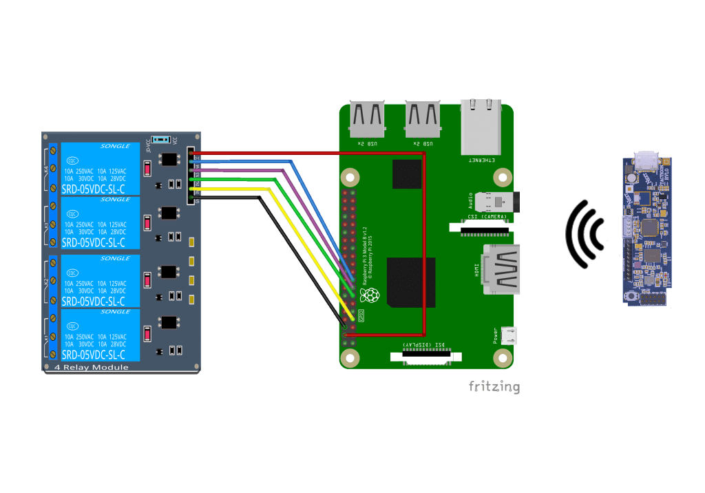
Let’s see now how to implement the application, starting from hardware parts; the 4-channels realy module was connected through a jumper to the Raspberry Pi single board computer 3, of which we have used pins 7, 11, 13 e 15 to provide the command signal to the inputs of the relay, while pins 4 and 6 are used to pick up the necessary 5V to the board and the GND line, which is the common mass power supply and control signals. The wiring of all necessary parts is shown in Pic. 2, where you can see which pins of the expansion connector of the Raspberry Pi have to be connected to the relay board.
The output terminals of the realy board allow lamps connection, which has to be done by interrupting the wire that carries the phase to the lighting bodies and by making it pass from the relays exchange, that’s between C and NO (normally open).
Remember that the connection to the lamps must be made with an electric cable with a suitable section and with suotable insulation as required to work with the 230 Vca of the electric grid; you must also pay due attention and take care of the insulation, keeping in mind that the pitches of the board relating to the relays and to the terminal blocks will be subjected to the grid voltage.
We therefore reccoment to enclose the 4-channels realy board in a plastic box, that will isolate both the board and the connections to the terminal blocks, thus preventing accidental contact and dangerous short circuits. By the way, if you want to perform a preliminary test of the whole, be sure that the floor on which you lay the circuits is made of insulating material (for example a wooden or laminated ant or melamine table).
Note that since THE TACTIGON is a board mainly created to make mobile applications, you must necessarily power it with battery in order to make it work applied to the hand; for this purpose, we suggest to use a lithium component (for example LiPo) equipped with a cable ending with a connector (female) with a 2,54 mm pitch to be inserted in the male one of the board. Battery must be 3,7V and about 150÷200 mAh capacity.
Picture 2
The Application
Let’s analyze what we did to make possible the communication between THE TACTIGON and Raspberry PI 3 via wireless interface Bluetooth Low Energy (Pic. 3).
The protocol
We begin by describing the communication protocol established for communication between TACTIGON and Raspberry Pi, which is very simple: two bytes are sent (it is possible to send up to 20 bytes in a package, for more complex protocols), with these features (byte values are hexadecimal):
- 0x0088: it activates the relays in order to switch on the lamps of side A only (see drawing in Pic. 1);
- 0x5A5A: it activates the relays in order to switch on the lamps of side B only (see Pic. 1);
- 0x00BB: it activates all the relays (it lights all lamps);
- 0x1515: it deactivates all the relays (it turns off all lamps).
Installation of the necessary modules and libraries for Gesture Controlled Lights
We can conclude the discussion on the
hardware and switch to the software, in order to see how to prepare and program
the Raspberry Pi. Here, or, better, in the system microSD-Card, the Raspbian
Stretch operating system must be installed, it was released at the end of
November 2017. The operating system must then be updated via APT and modules
and libraries necessary to the controller programming must be installed in it.
We will see below all the operations to be performed.
For the correct functioning of the project, in particular of Bluetooth Low
Energy communication, it is necessary to install the latest version of BlueZ,
by downloading the sources from the site http://www.bluez.org/download/ .
Before package compiling, it is necessary to install the dependences necessary
for the compilation, by launching these two commands from the terminal:
How to proceed:
sudo apt-get update
sudo apt-get install -y libusb- dev libdbus-1-dev libglib2.0- dev libudev-dev libical-dev libreadline-dev
The -y parameter will allow installation of the listed packages without requiring further confirmation from the user. Once the installation of the sources has been completed, we can proceed with the compilation of the BlueZ module using the standard commands:
./configure
make
sudo make install
If the procedure ends without errors, we can go to enable the experimental functions by modifying BlueZ configuration file, through the commands:
sudo nano /lib/systemd/system/ bluetooth.service
We search line ExecStart in the [Service] section and at the end we add the string:
–experimental
Almost there!
On the keyboard connected to Raspberry
Pi we press the CTRL-O key combination, then the enter key to save the newly
edited file and CTRL-X to close the nano text editor.
Now let’s restart the daemon to get it load the new configuration:
sudo systemctl daemon-reload
With the following command we restart the service if it is already running:
sudo systemctl restart bluetooth
systemctl status
We check that everything is installed correctly by using the status command:
systemctl status bluetooth
and we make sure that the string –experimental is now present:
bluetooth.service – Bluetooth service
Loaded: loaded (/lib/systemd/ system/bluetooth.service; disabled)
Active: active (running) since Mon 2018-02-12 09:18:15
UTC; 15s ago
Docs: man:bluetoothd(8) Main PID: 1022 (bluetoothd)
Status: “Running”
CGroup: /system.slice/ bluetooth.service
??1022 /usr/local/
libexec/bluetooth/bluetoothd –experimental
Python libraries
To install python bluepy library it is
nècessary to install python-pip, as well as some support libraries.
We then launch the commands:
sudo apt-get install python-pip sudo
apt-get install libglib2.0- dev
sudo pip install bluepy
We’re now ready to proceed with the script python writing for relays control.
Raspberry Pi and Python
We have seen that the firmware loaded on The Tactigon sends data to Raspberry Pi when a gesture is detected; it is therefore necessary that the notification system provided by the standard Bluetooth Low Energy, in order to save hardware resources on the Raspberry Pi 3 single board computer.
To do this, you need to subscribe to a feature, which will call a callback if a message is received. The installed library, bluepy, facilitates code writing, offering a class, called DefaultDelegate, which we will implement to manage the notifications. The other libraries to be imported are RPi.GPIO, which are necessary to control the 4 GPIOs used for relays, as well as binascii and struct for the management of binary data received from The Tactigon controller.
After class definition MyDelegate (DefaultDelegate), we have to implement funtion handleNotification (self, cHandle, data) that will called when there will be a Bluetooth Low Energy notification regarding the signed feature.
Instructions:
val=binascii.b2a_hex(data) val=binascii.unhexlify(val)
val = struct.unpack(‘H’, val)[0]
we are recomposing the message received from The Tactigon in order to compare it with the values declared in the protocol and then perfume the requested action.
Now that the callback is ready, let’s analyze how to use it and how to subscribe to the feature. For this purpose we need to know the MAC Address of The Tactigon, as well as UUID of the service and the featureBluetooth Low Energy to read. To set notify on the feature, we have to write in a characteristic, 0x2902, within the same service as the feature to be subscribed.
The instruction for this are:
#SET NOTIFICATION
notifyTactigon = tactigonService. getDescriptors(forUUID=0x2902) [0]
notifyTactigon.write(struct. pack(‘<bb’, 0x01, 0x00))
Once subscription has started, we can wait for messages sent by The Tactigon:
#WAIT FOR NOTIFICATIONS
try:
while True: if
p.waitForNotifications(1.0):
continue
except:
print(“Terminated”)
So, we have explained the software part of the project concerning the Raspberry Pi board.
The Tactigon Sketch
Let’s move now on to the “Arduino” side : the firmware, or the sketch loaded in the Tactigon board analyzes the position of the board and then sends the message via Bluetooth Low Energy.
The Tactigon evaluates its position at a frequency of 50Hz and every time the microcontroller finds a programmed position, it sends the data via Bluetooth Low Energy and prevents, for about 0,5 seconds, sending of other messages to leave time to Raspberry Pi 3 to evaluate the message and activate board’s relays. In addition to this momentary block, The Tactigon will not send more messages related to the last detected position until a different one is detected.
Here as it follows you can find the code.
if (!lastSupX && accData.x > threshold) {
lastSupX = true; lastInfX = false; lastInfY = false; lastSupY = false; buffData[0] = 0x00; buffData[1] = 0xBB; flash();
bleChar.
update(buffData);
justSent = true;
}
This code, repeated for the two x and y axes, allows to detect the exact position of the board. The Boolean variable lastSupX is used,indeed, to avoid that the same configuration is repeatedly sent and so too lightsn the load on to the Raspberry Pi 3; this detail, although not very relevant in this application, becomes important when The Tactigon has to deal with applications that are much more demanding from calculation point of view.
Once this control is passed, this condition is evalued:
accData.x > threshold
here threshold parameter is an acceleration one, expressed in m/s², which allows to establish The Tactigon sensitivity to the “gesture” that we are going to perfom; in other words, threshold allows to detect the gesture movement over a certain speed and to ignore the slow movements of the hands, leaving us free to move them without giving wrong commands.
accData.x is instead the acceleration component action recorded by The Tactigon on the X axis.
Well, we have also explained the software part of the project.
Conclusions
The Lights Control Through Gesture project we have proposed is just an example of the application, which can be adapted to other cases beyond lights control. Among other applications we can include media player control, machine drive control, drives and
appliances, but also much else that requires or accepts the on/off command.
The possibility to define, in The Tactigon, acceleration threshold above which to consider hand movements, allows you to customize project adapting it to the physical needs of the person, both the situation and the environment in which they perform the gesture.
Remember to download the source code for “Lights control through gesture” project and subscribe to our YouTube channel!